


Introduction and terminology
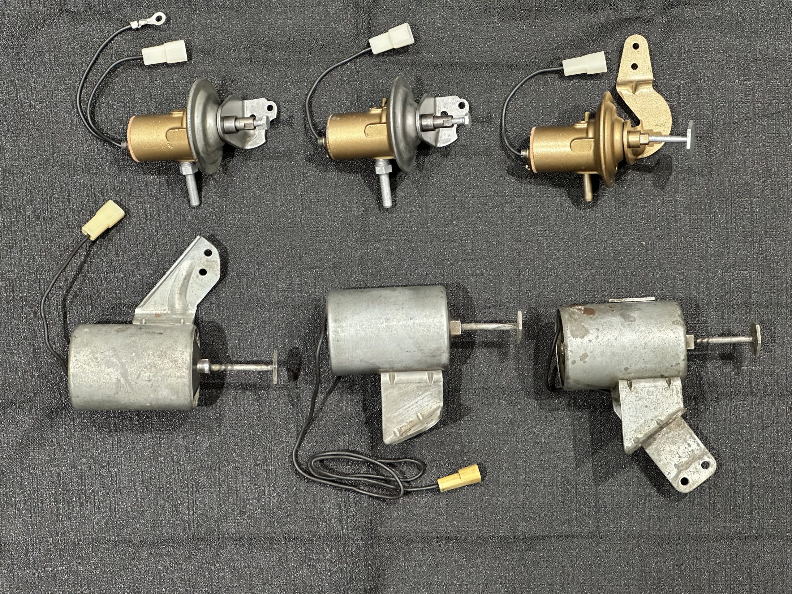
Corvair Factory Air Conditioning was a relatively rare option, available 1961-1967. Beginning in 1962, Corvairs with C.A.C. (Car Air Conditioning) were equipped with an idle control assembly designed to increase the idle speed when the compressor was running, to prevent engine stalling. Between 1962 and 1967, six different versions of the Idle Speed-up Control assemblies were produced.
Note: Although Chevrolet’s official name for these units is “Idle Speed-up Control Assembly”, they are more commonly known as “Fast Idle Solenoids”. Hereafter in this article I shall refer to these units by the abbreviation “ISCA”.
1961
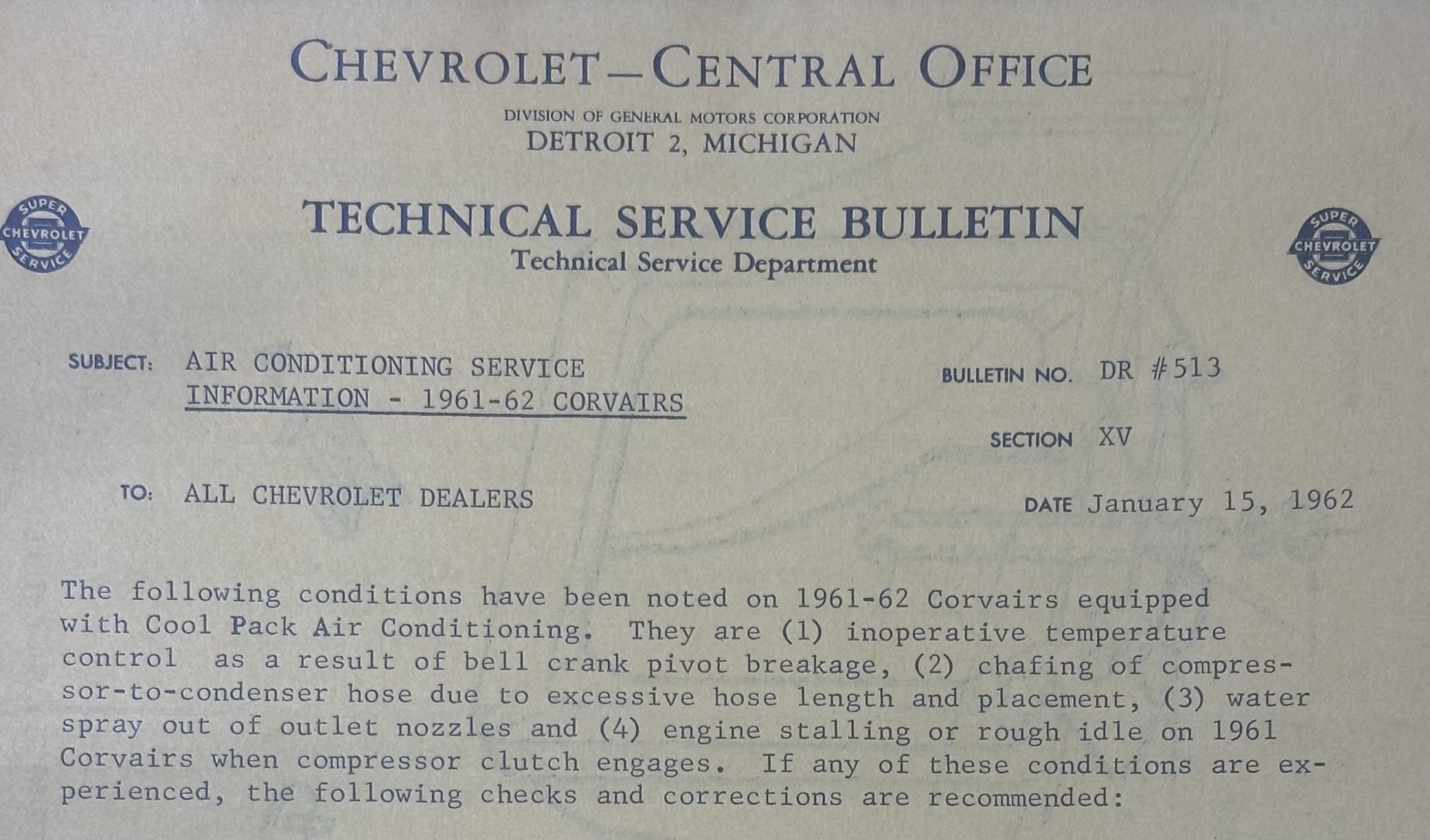
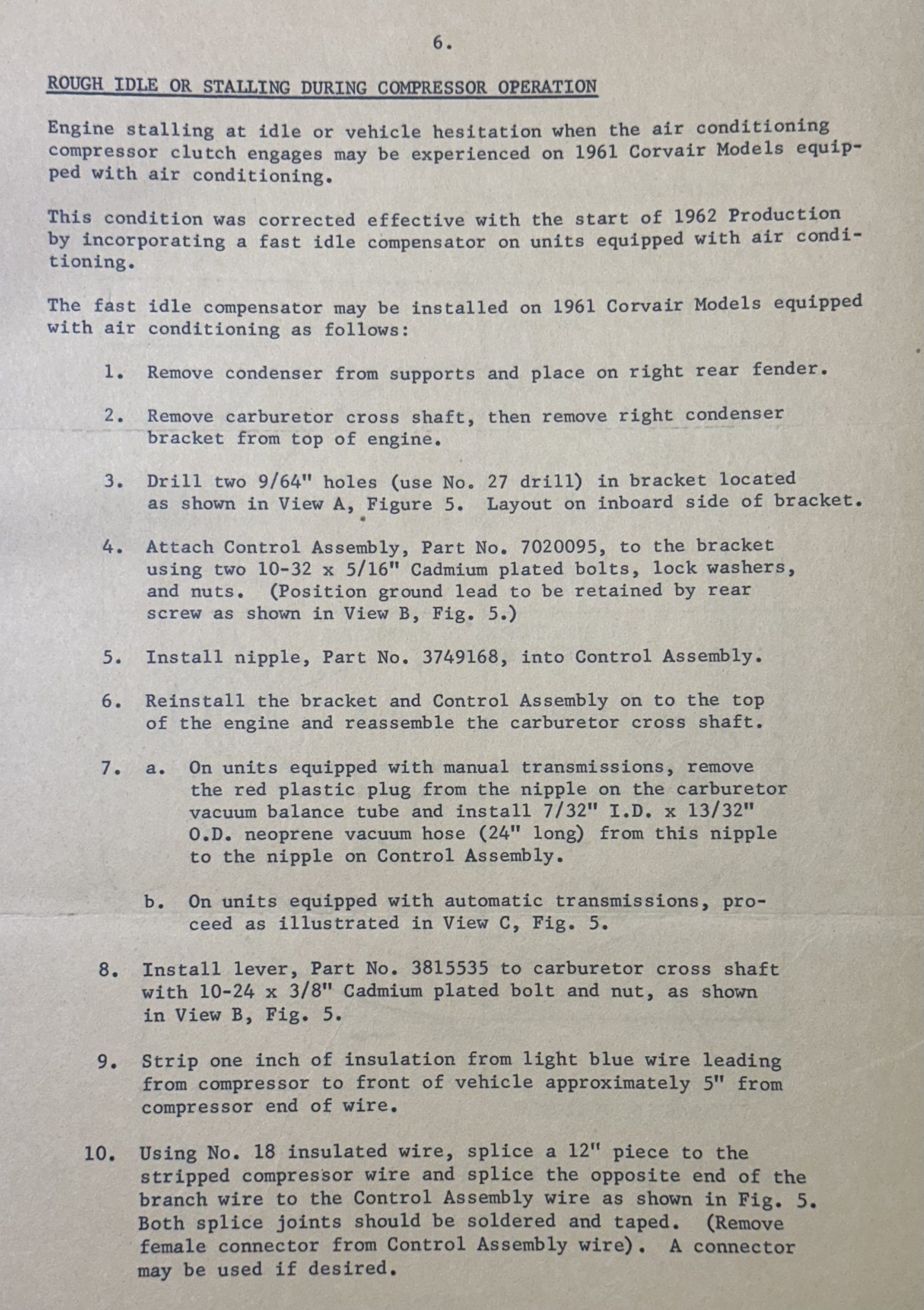
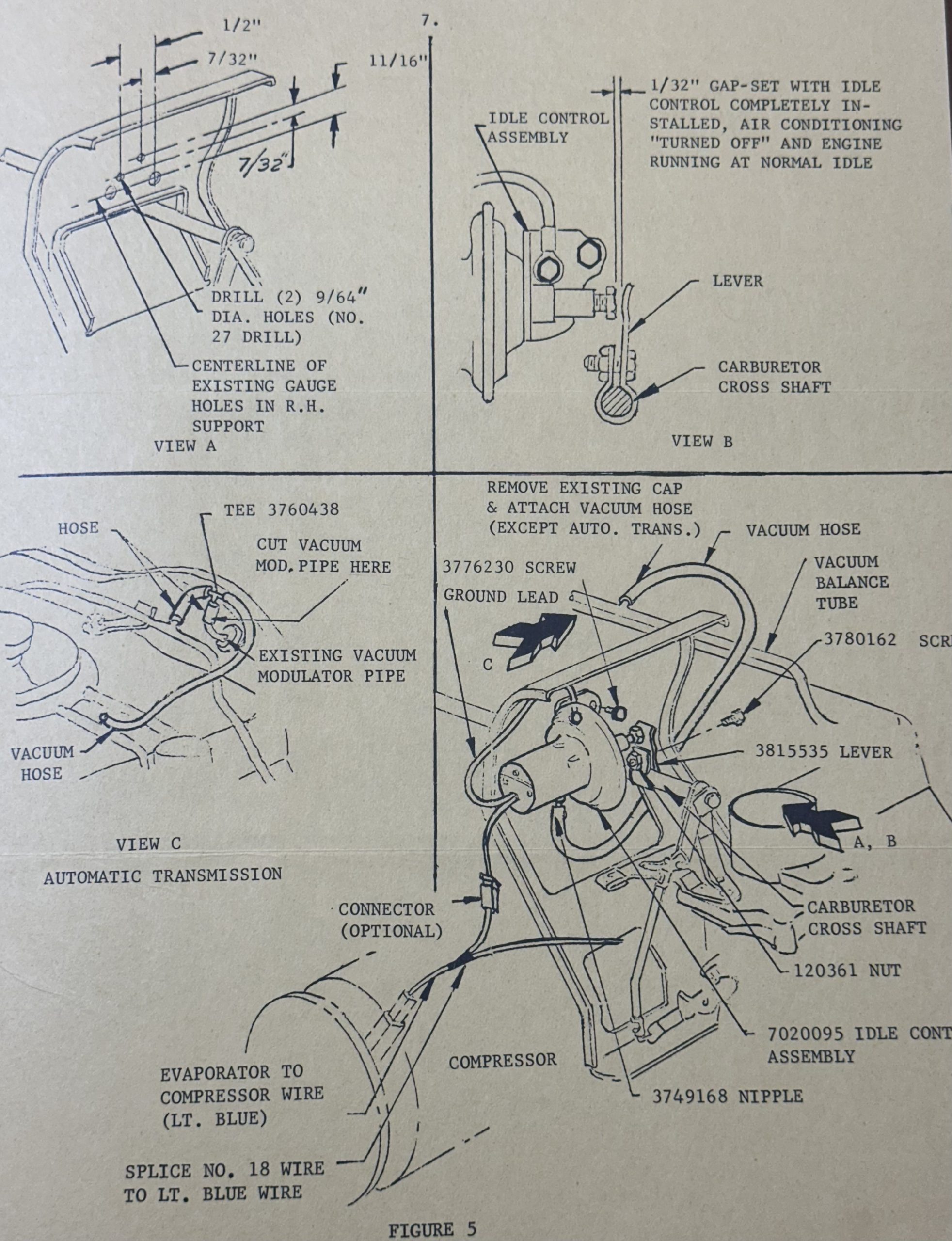
Corvair Air Conditioning was first introduced in March 1961, using a Frigidaire A5 compressor (painted green to identify it as a reverse rotation unit). This option did not initially include an ISCA; however, Chevrolet TSB DR #513, issued on January 15, 1962, directed dealers to install one if the owner complained of engine stalling or rough idle. The ISCA to be installed was identical to those installed on all 1962 CAC Corvairs.
1962
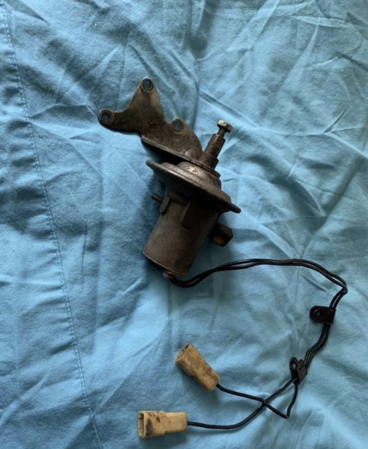
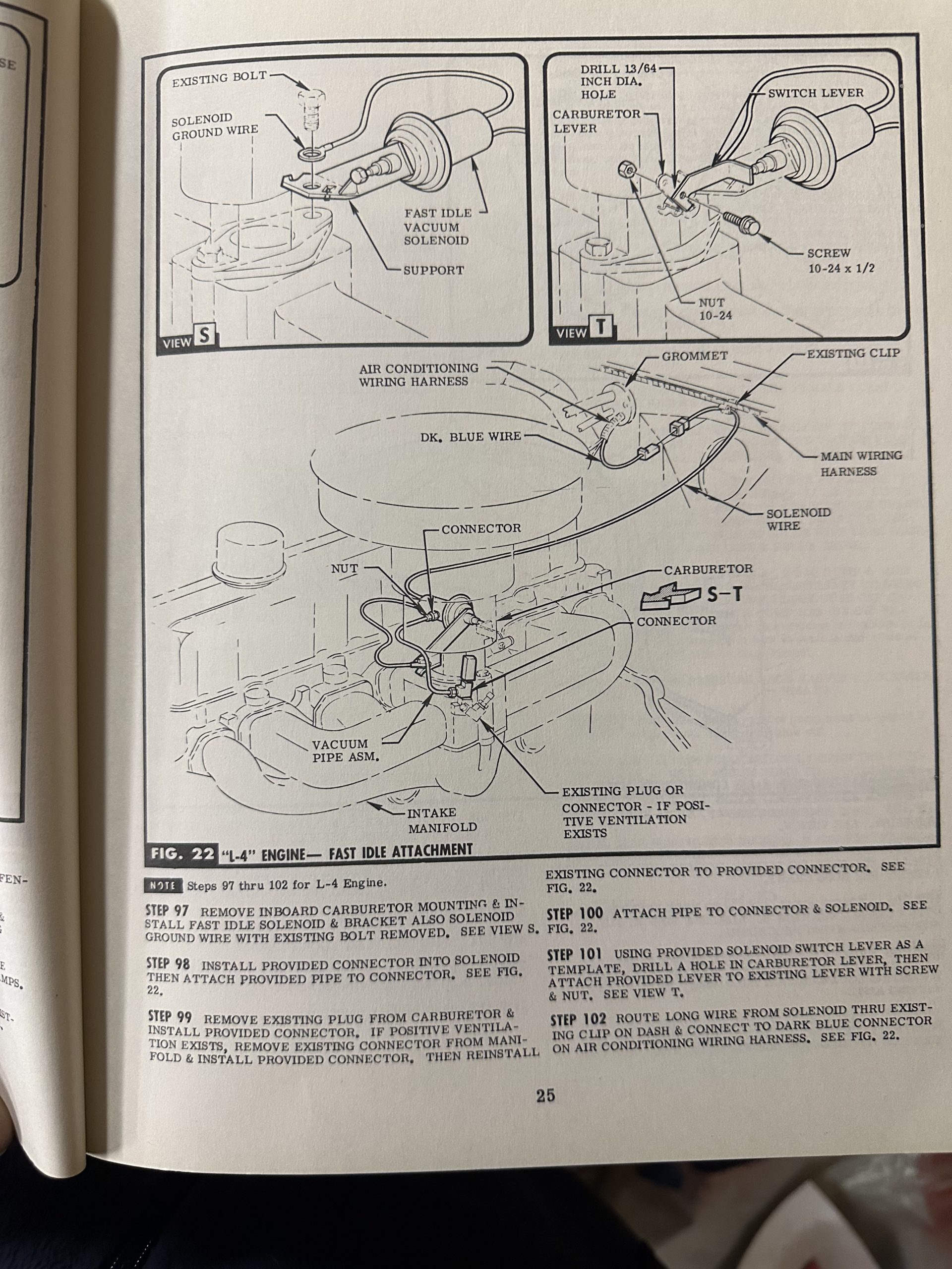
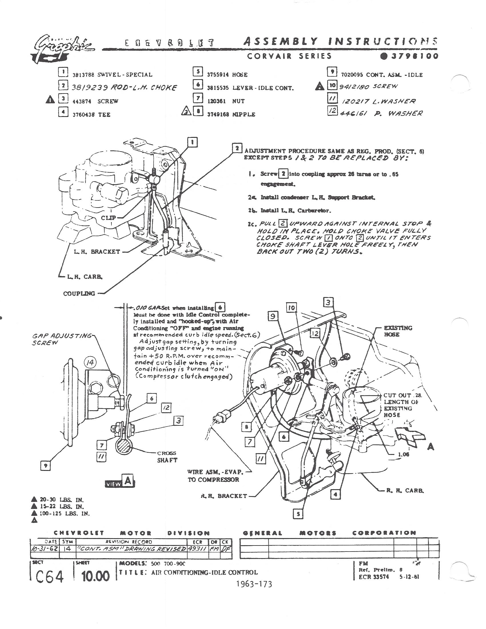
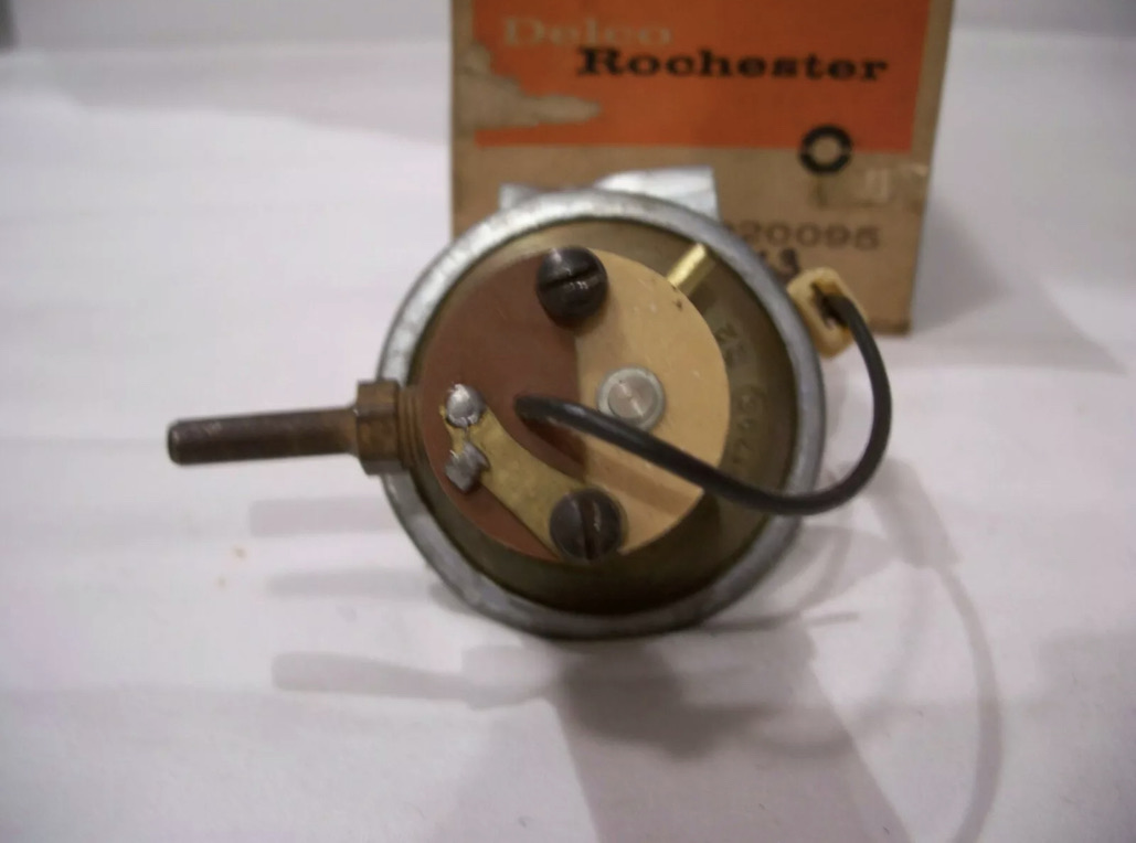
ISCAs were required on all 1962 CAC Corvairs, but the device was not unique to Corvair. Other GM cars also used them (with different mounting brackets), as pictured below:
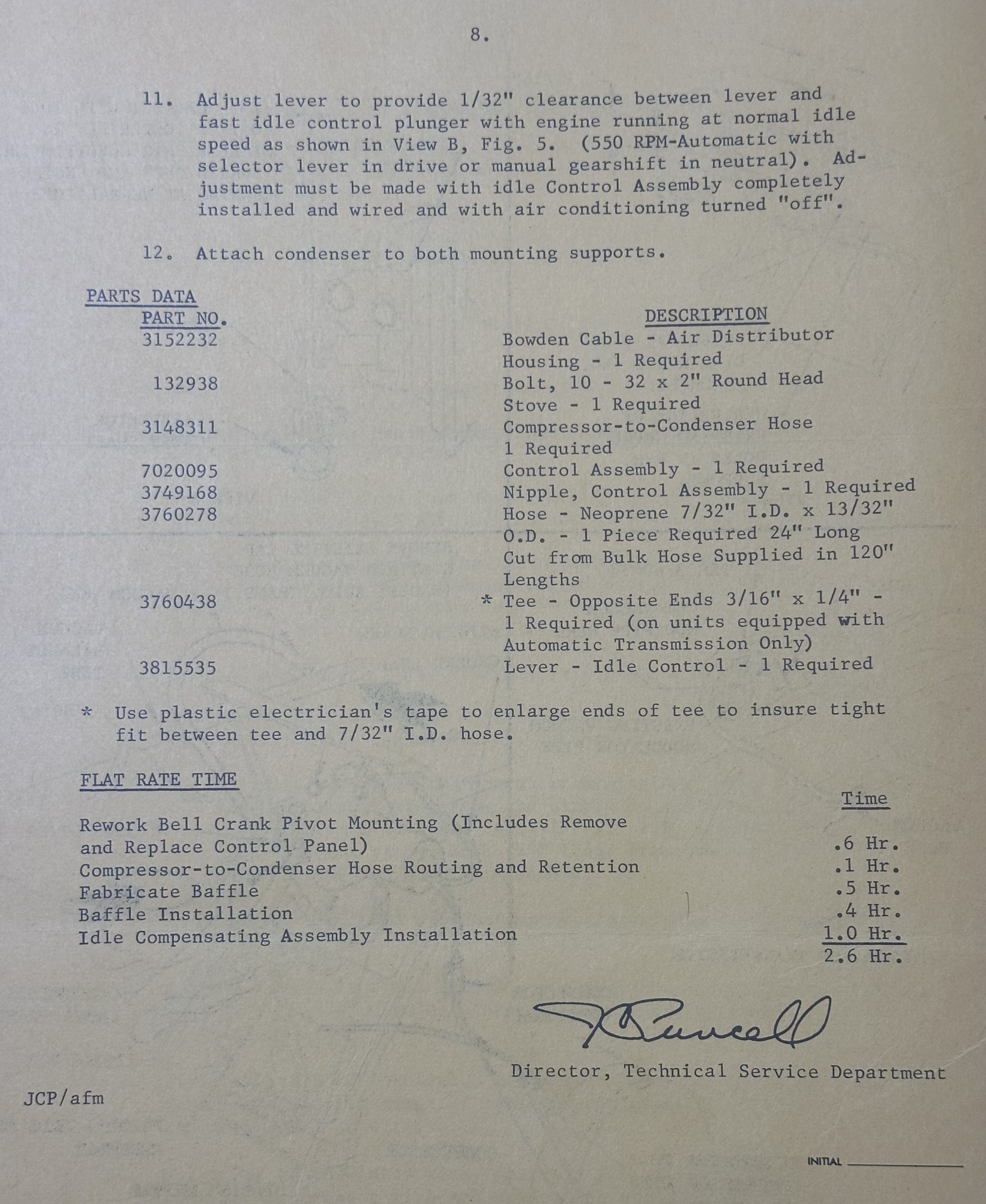
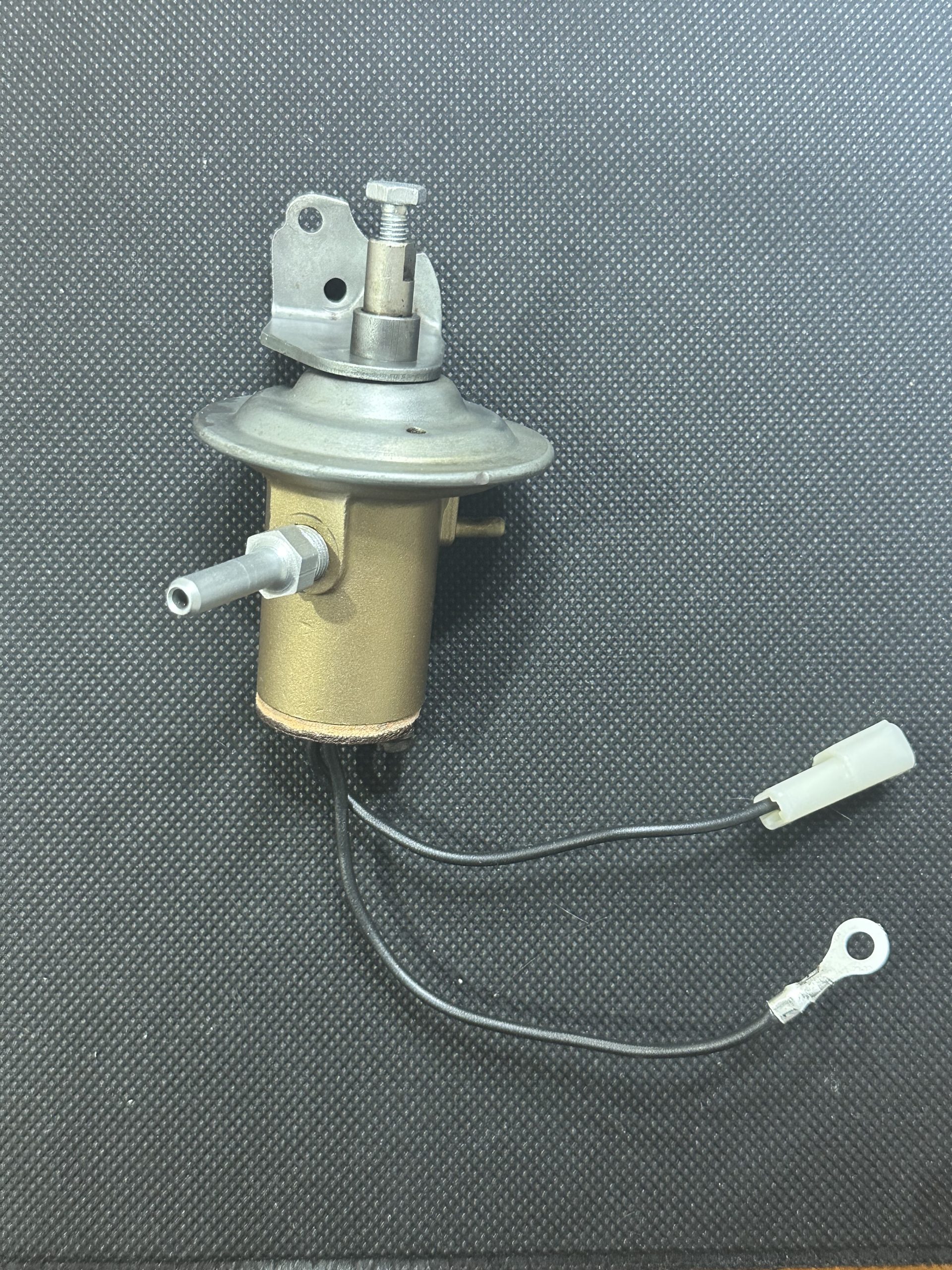
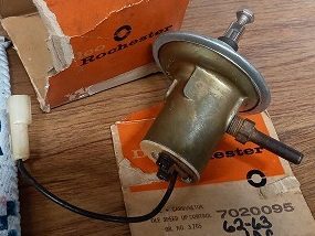
The 1962 Corvair version is part number 7020095, and has two wires exiting the phenolic base; one with a bare ring terminal that is attached to ground, and the other an insulated male Packard 56 terminal that connects to the compressor clutch.
How it works
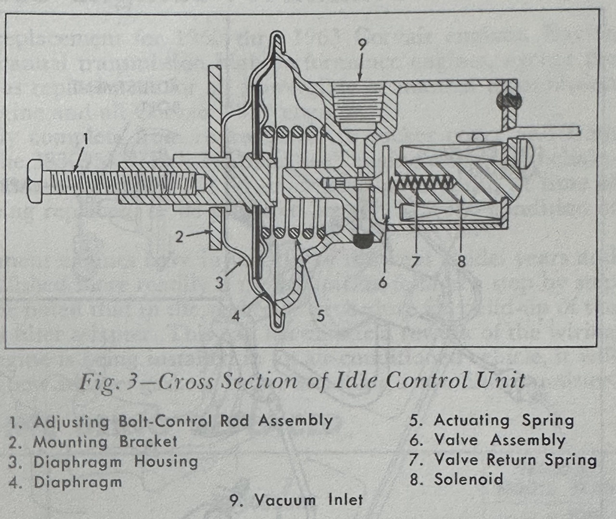
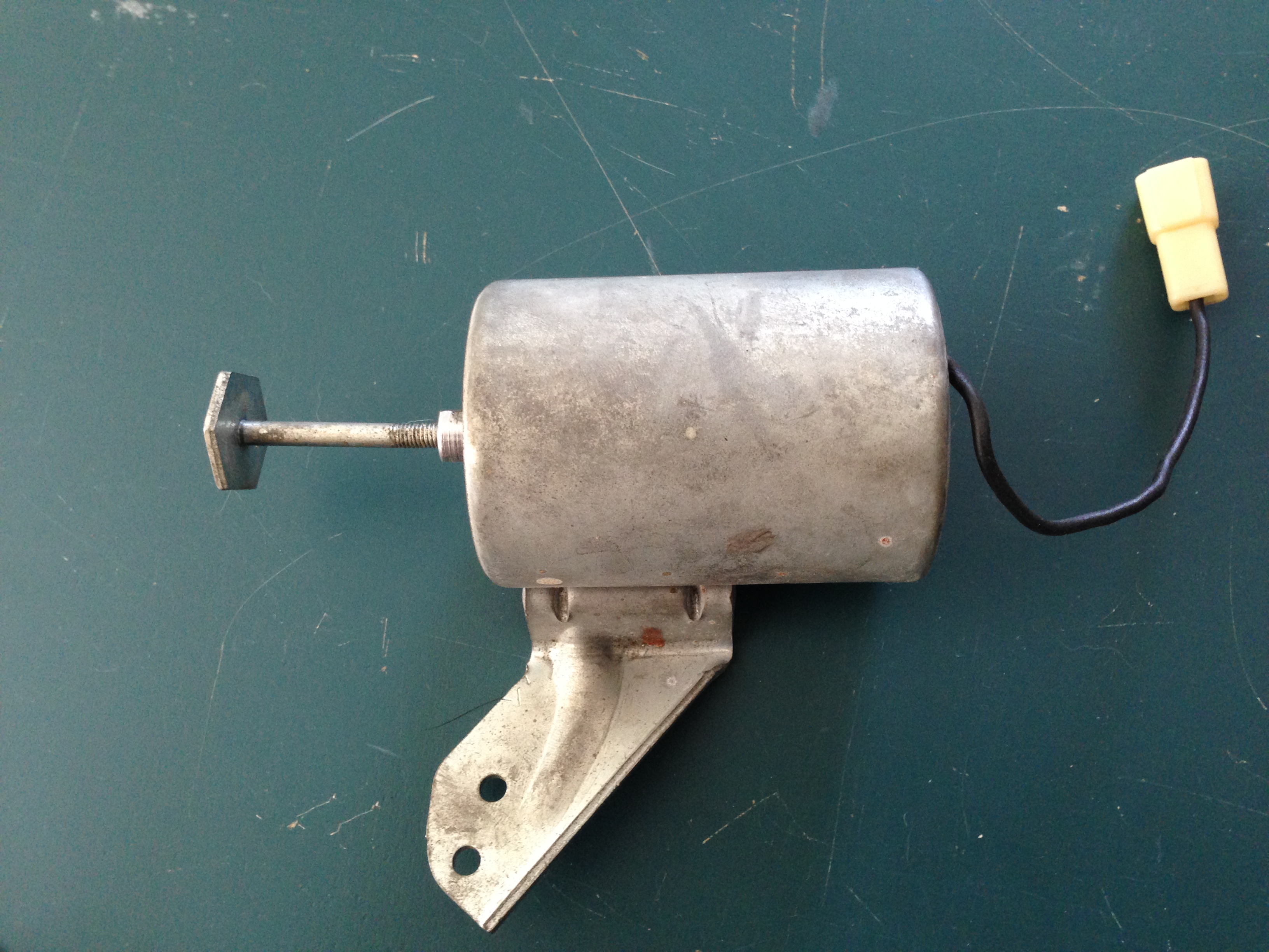
This is a vacuum-electric unit with a piston that extends to push on a finger mounted to the accelerator linkage whenever the compressor clutch is activated; hence, this device is commonly called the “pusher” unit. The device consists of a housing for the solenoid integrated with the vacuum ports and the diaphragm housing. Inside the diaphragm housing is a powerful spring which pushes the piston and its attached rubber diaphragm. A small brass rod valve attached to a ferrous metal disc is inserted in a hole at right angles to the vacuum port. A solenoid coil with a small spring inside is secured to the housing with two screws.
Whenever the compressor clutch is inactive, the solenoid coil is also unpowered, allowing the small spring to push the metal disc away from the coil, thereby seating the brass valve and opening the vacuum port to the diaphragm. When the engine has sufficient vacuum (engine is idling), the vacuum overcomes the push of the large diaphragm spring and retracts the piston away from the throttle linnkage finger.
Whenever the compressor clutch is active, power is supplied to the solenoid coil to lift the metal disc, pulling the brass rod up. This vents the diaphragm housing and blocks the incoming vacuum port, causing the diaphragm spring to push the piston forward to press on the accelerator linkage and speed up the idle. Note that the solenoid coil is powered whenever the compressor clutch is powered, and this happens at any engine speed; however, only at idle is the accelerator linkage in position to be affected by the extension of the piston.
The basic flaw in this design is that anything causing loss of vacuum to the device (blockage or leakage in the hose, etc.) will result in abnormally fast idle when the AC is not running, as the piston will always remain in extended position and contact the accelerator linkage at idle.
1963
The only change in 1963 was the elimination of the ground wire. It was replaced by a brass “finger” riveted to the phenolic base, grounded by way of one of the base attaching screws. In spite of the modification, it retained the same part number, 7020095.
Replacement Kits
1962-63 ISCAs used very small brass rod “valves”- approximately 1/16″ diameter. Over time, these valves were prone to wear, breakage, or separation from the metal disc, any of which would render the unit inoperative. Back in the day, replacement kits for both the solenoid and diaphragm units were available. Other than the part numbers, I have found no other information about these kits:
- 7021852 – Solenoid kit, idle speed-up control, 1962-63 Corvair w/ C.A. C.
- 7020810 – Diaphragm Assembly, idle speed-up control, 1962-63 Corvair w/ C.A.C.
1964
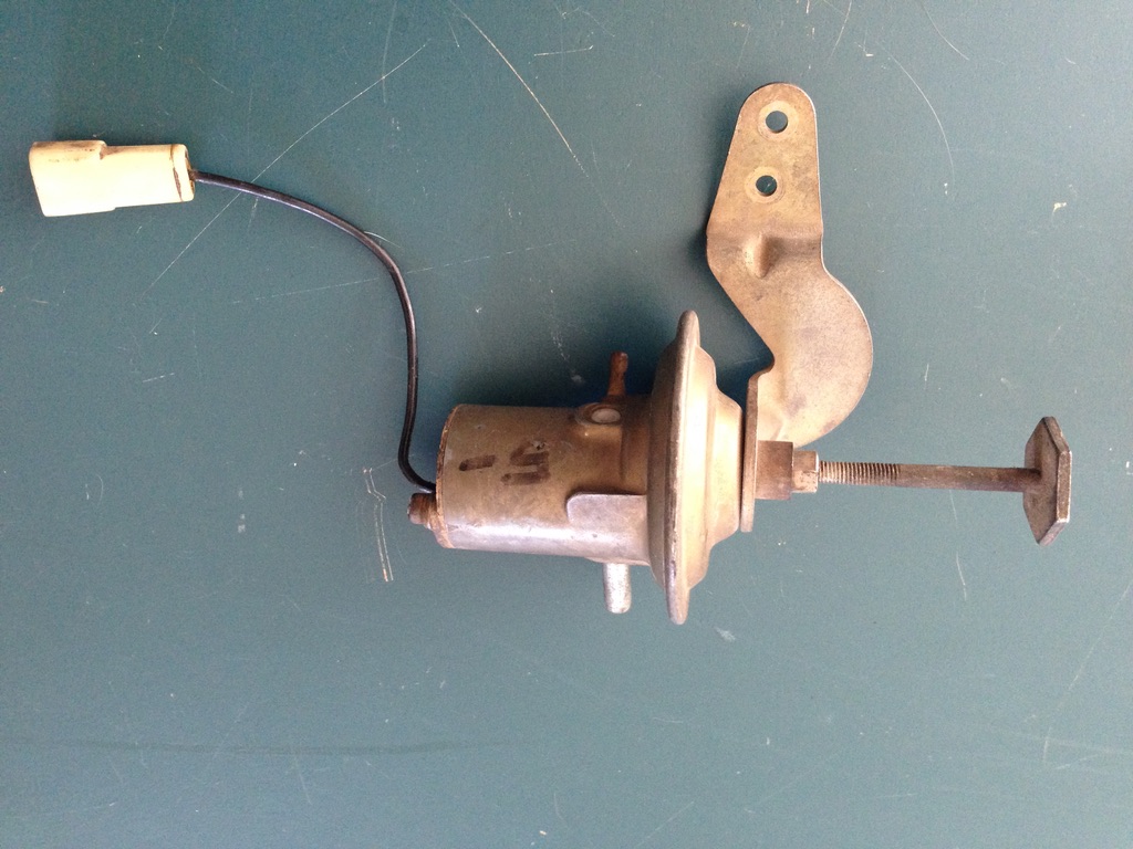
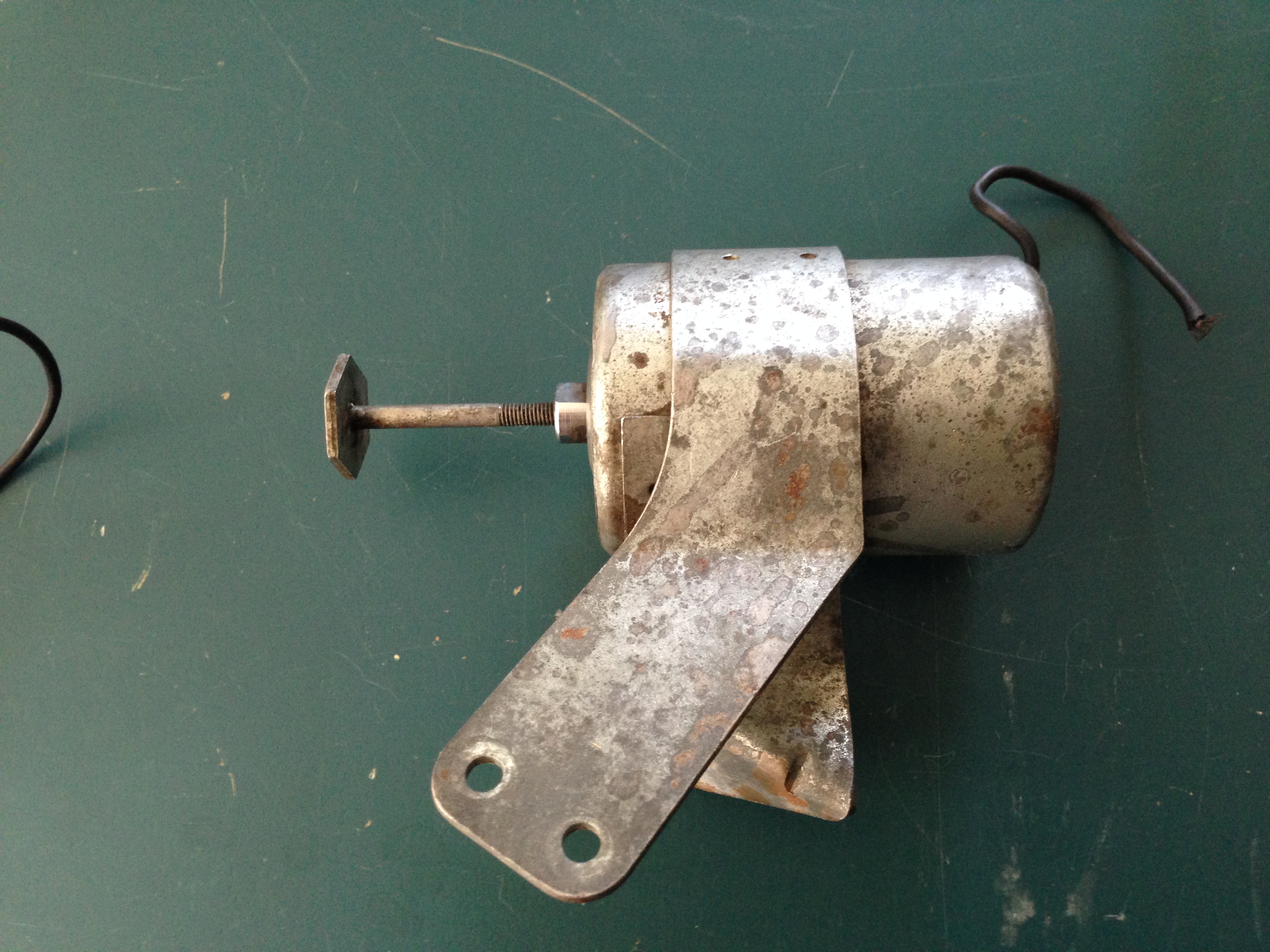
1964 brought many changes to the Corvair engine, and the ISCA was one of them. Although similar in appearance, the device operates in the opposite direction of the 1962-63 units; it pulls on a fork mounted to the accelerator linkage. Thus, these units are called “pullers”.
Internally, this unit uses a larger brass rod valve (1/8′ diameter) that blocks the vacuum when the compressor is not running and directs it to the diaphragm when the compressor is engaged. The diaphragm housing has a weaker spring, as its only function now is to passively extend the piston when the compressor disengages. The solenoid coil and spring are identical to the 1963 units. Externally, the piston now has a pulling rod with a 3/4″ hex head attached.
This design corrected the basic flaw in the earlier design; a failure to supply vacuum to this design simply prevents it from functioning when the compressor is running, but will not affect idle speed otherwise.
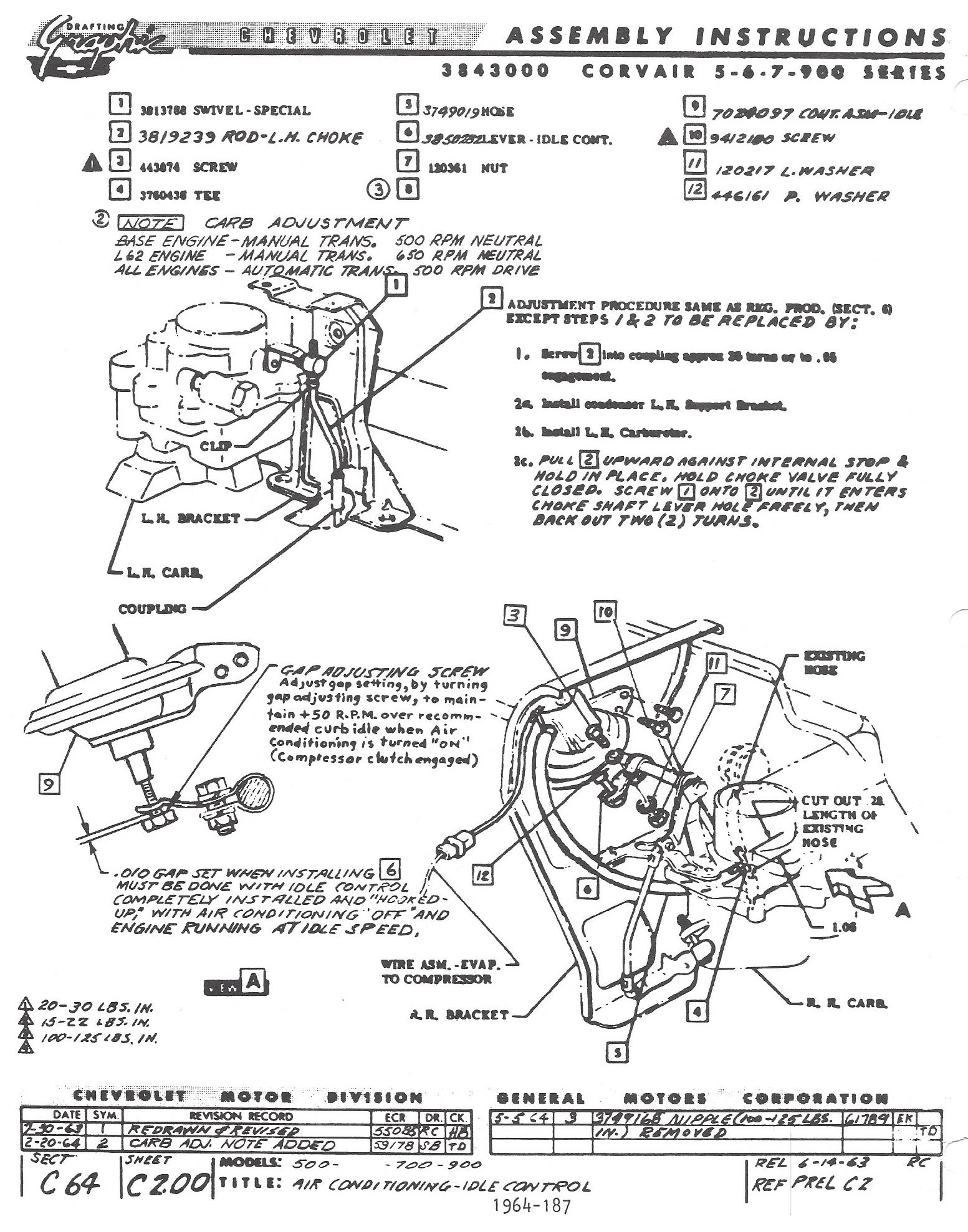
The GM part numbers for the 1964 ISCAs are as follows:
- 7024097 Idle Speed-up Control Assembly
- 7027830 Diaphragm and Bracket Assembly
- 7031406 Solenoid Kit
- 7027838 Contact Screw (the part the screws into the piston and pulls on the throttle)
1965
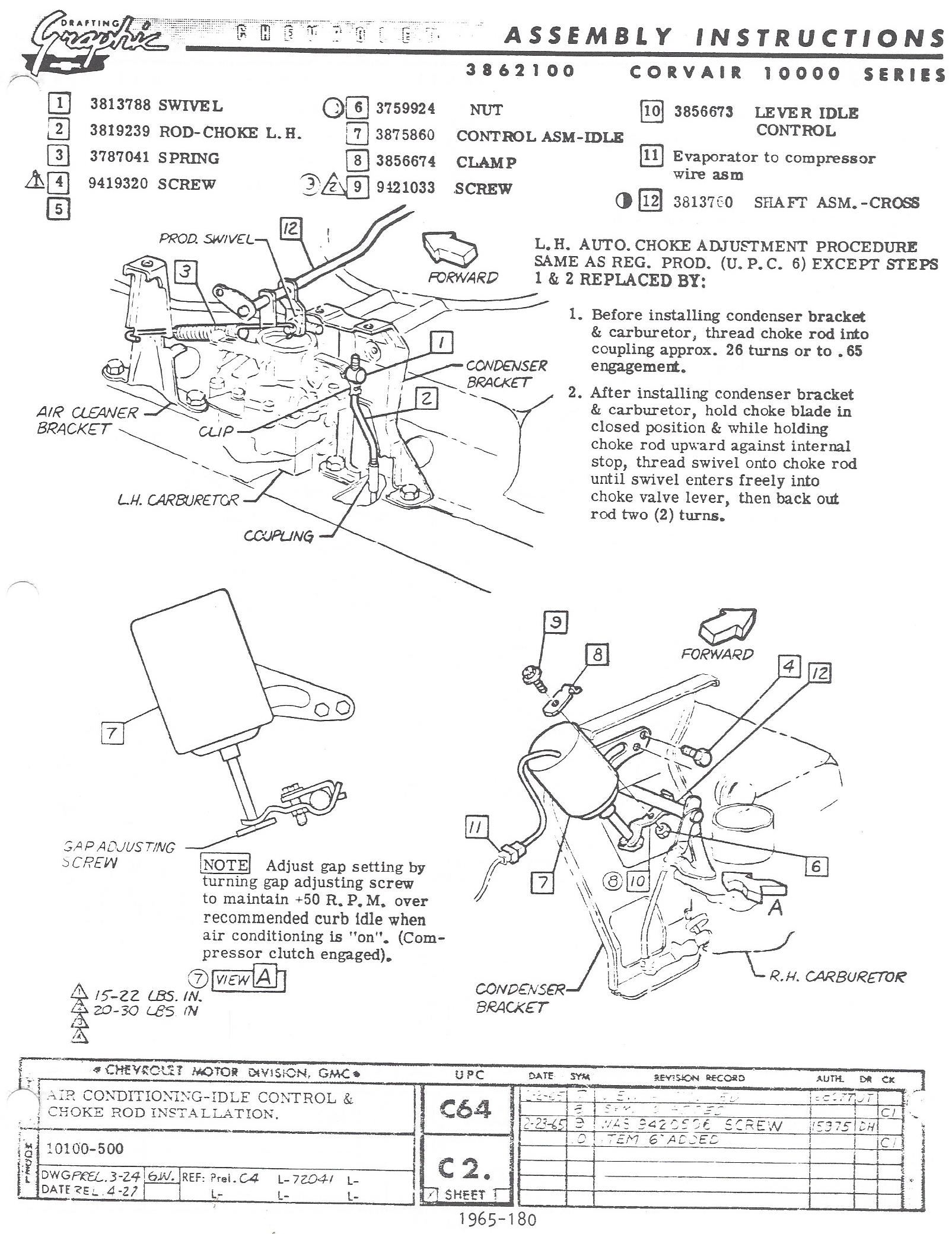
1965 models initially continued to use the 1964 ISCA but midyear (January or February 1965?) it was replaced by an all-electric version, part # 3875860. This unit thus became the de facto replacement for all previous units. Although it required more electricity to operate than the smaller solenoid in the prior units, it undoubtedly proved more reliable in the long run.
/
1966 (first design)
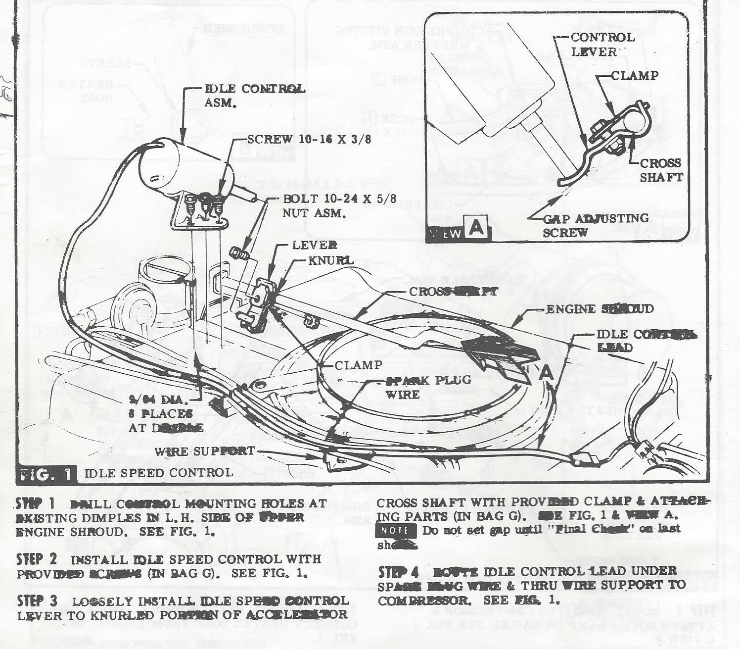
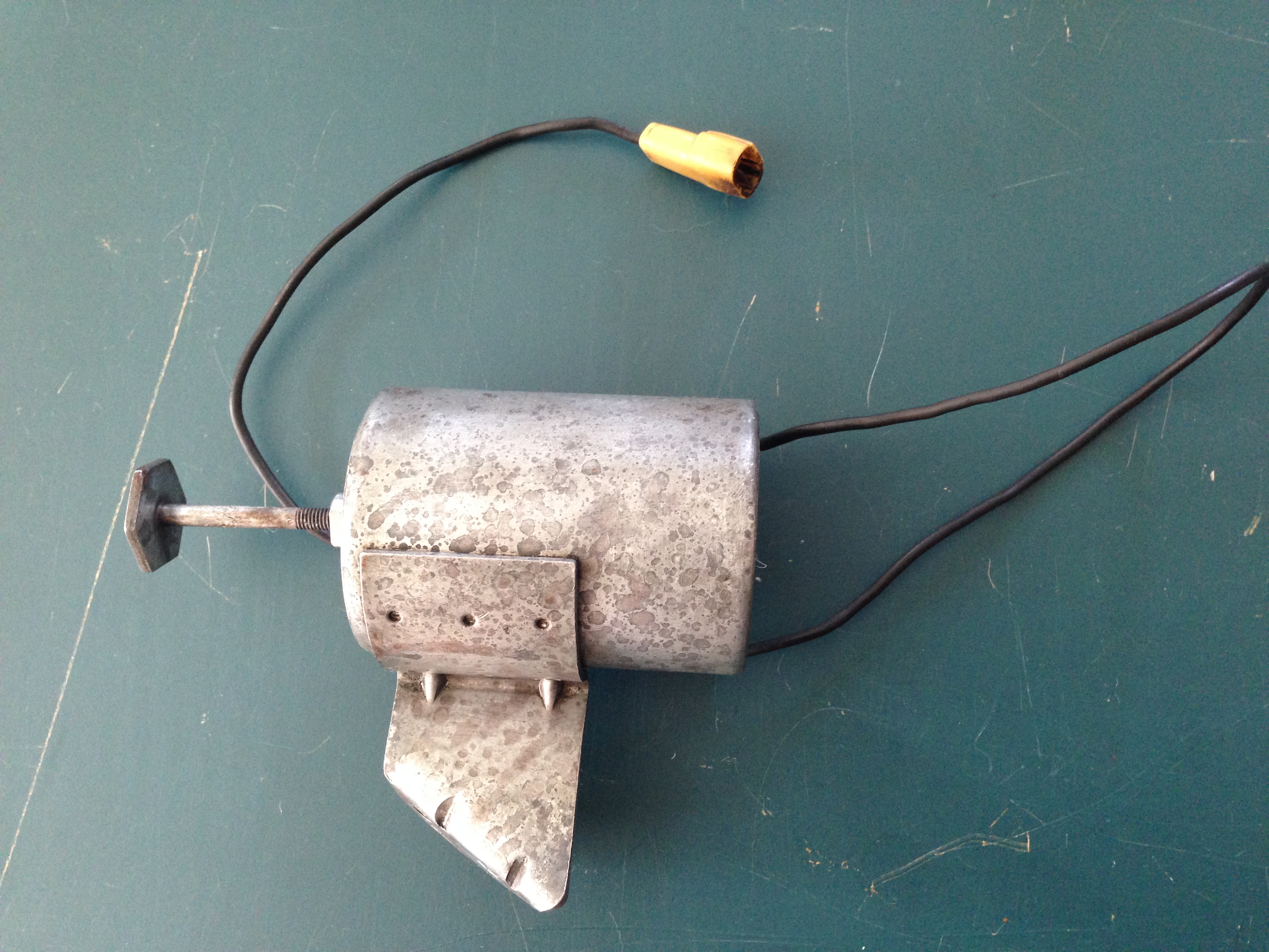
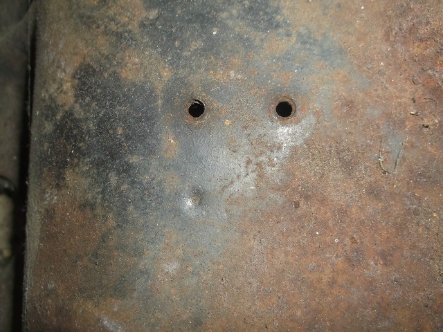
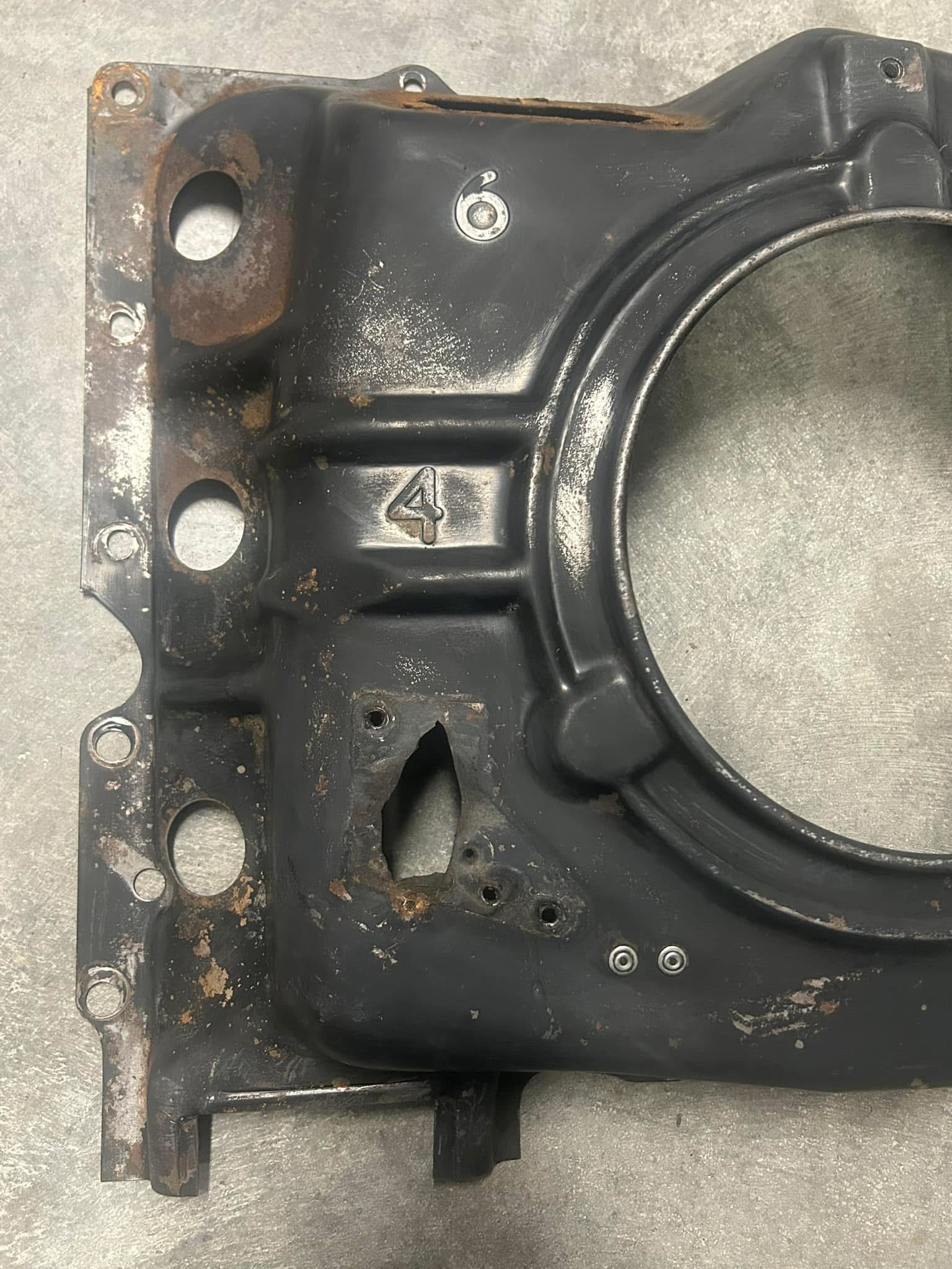
1966 used the same all-electric unit but with a different bracket welded onto it which allowed placement on left side of the engine, bolted directly to the top engine shroud. This proved to be problematic as the weight of the solenoid, combined with engine vibrations, would eventually cause the screws to rip through the top shroud.
1966-67 (Second Design)
The single leg unit was replaced mid-year when an additional support leg was added.
1967 was the final year for Corvair Air Conditioning and there were no further changes to the ISCA that year, so the final count is 6 different assemblies for the six years of AC options, all pictured together at the beginning of this article.
Repairing Vacuum-Electric Assemblies
Over time, these assemblies have become worn or broken, making working units more and more difficult to find. The vacuum-electric units can suffer from a variety of maladies, including:
- Corrosion of moving parts (piston, valve)
- Torn or deteriorated rubber diaphragms
- Worn or broken brass valves
- Broken or deteriorated solenoid wiring
- Worn or missing valve return springs
- Separation of solenoid core from base
The all-electric units are more durable, but they can also suffer from corrosion and broken wiring.
As it turns out, it is generally possible to rehabilitate most of the issues that render the early units inoperative. (The all-electric units are sealed and therefore difficult to fix if the wire breaks off inside.)
Begin by completely disassembling the unit.
Base screws & lock washers, Solenoid (base, coil & core), valve return spring, Valve, Diaphragm body with contact screw
First, test for diaphragm function by applying vacuum to the vacuum port on the side of the housing and (with the valve removed) placing your finger over the valve hole inside the housing; the piston should move inward. Note that the ’62-’63 units require a stronger vacuum to move the piston. If there is no movement, check to make sure the vacuum port is not blocked and the piston is not frozen in the housing by corrosion. You should be able to push the piston in by hand; if not, gently tap it to see if you can free it up. If the piston moves OK by hand, and you have assured the vacuum ports are not blocked, but piston does not move when you apply vacuum and cover the internal port, the diaphragm is most likely damaged and you should find another unit.
I have disassembled a few diaphragm housings and determined that while it is possible to repair them, as long as other working units remain available, it is not worth the effort.


Fortunately, Diaphragm failure is uncommon, so most units can be cleaned, (soak in Evapo-Rust if needed to remove rust), dried, degreased, and recoated. Use masking to keep fluids and coatings from entering the diaphragm housing or vacuum ports.
The diaphragm covers and brackets are steel, originally cadmium plated (’64-64 were additionally gold chromated). The rest of the housing is pot metal, originally gold chromated. Unfortunately, it is not possible to duplicate this without disassembling the covers from the rest of the housing, which is likely to damage both. Instead, I coat the housings with a bronze paint that roughly duplicates the original appearance and clear coat the “bare metal” parts.

The valves are small brass rods, turned to the proper size and shape. These are difficult, but not impossible to reproduce. A small metal lathe is essential for making the ’62-’63 valves, but it is possible to make the larger ’64-’65 valves using just an electric drill, vise, and metal file. The new valves can then be attached to the metal discs with solder.
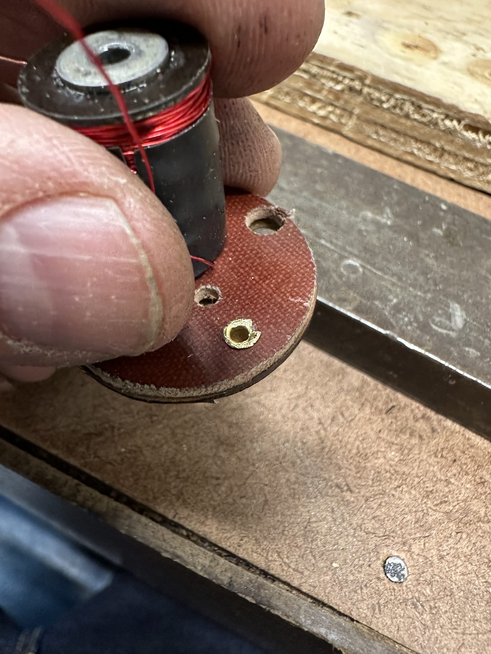
If the solenoid core has separated from the phenolic base, it is necessary to manufacture a new base, as the old base will have an enlarged hole. Drill the solenoid core hole in the new base to 1/4″. The core will have a mushroomed tip, as it was originally inserted into the base and then peened to secure it. By freezing the core (in liquid Nitrogen or even Dry Ice), it will shrink just enough to allow it to be tapped into the 1/4″ hole to secure a tight fit. The new base can then be riveted to the original upper half piece and brass “finger. It’s important to remember to install a phenolic or fiber washer to the core before installing it to the base.

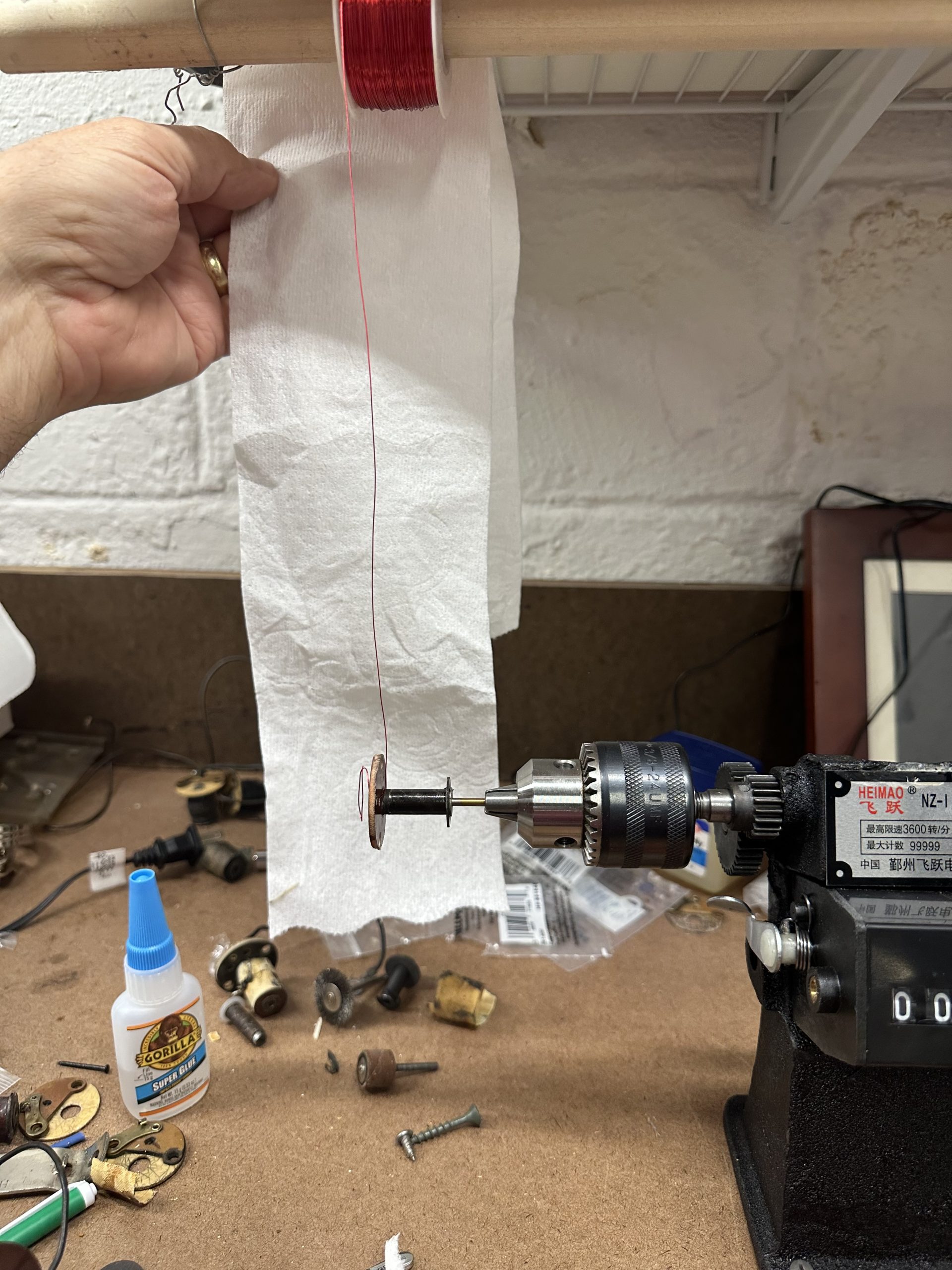
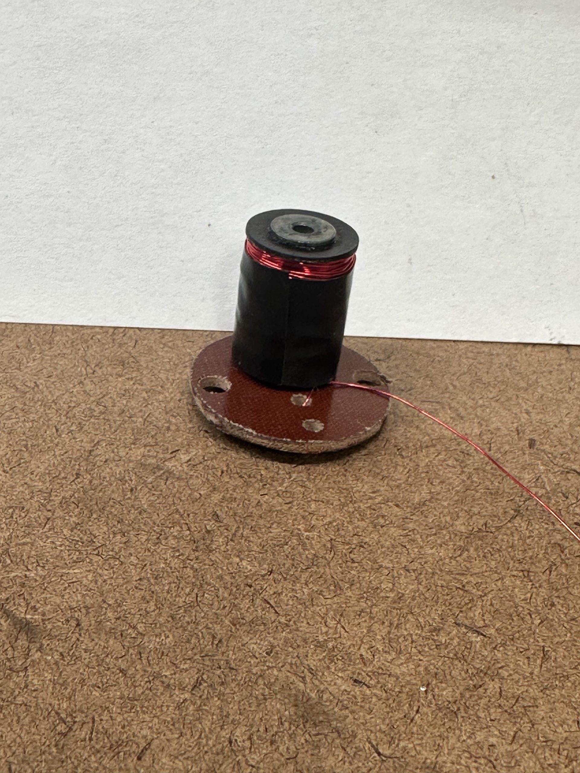
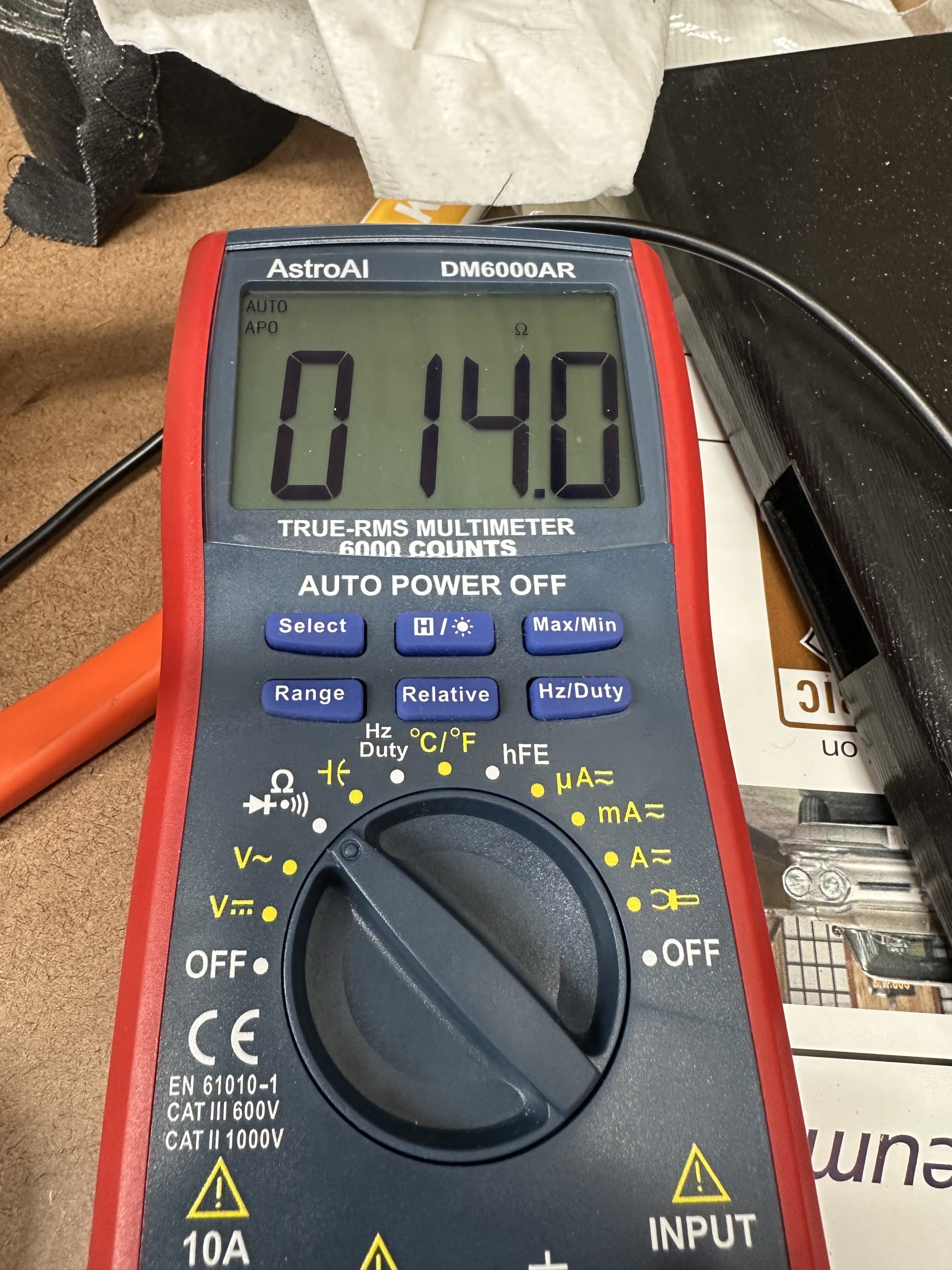
After the core is securely attached to the base, apply a one-layer coating of cloth or paper tape to the core. It is now ready to be rewound. Testing of multiple original cores finds they have a finished resistance of 14-15.5 ohms, with about 1100 turns of wire. I have found that 30g magnet wire works best to rewind coils for these units. It is essential to have some sort of coil winding machine to keep track of the number of turns and to control the process. Windings should be neat and tight. When winding is completed, finish the coil by soldering the connections to insulated 18g wire (for the compressor clutch lead and 1962 ground lead) or the brass finger riveted to phenolic base (ground for 1963-65 coils). The 18g insulated wire(s) pass through a small hole in the center of the phenolic base. Finish the coil by crimping new connectors and attach terminal cover.

If the valve return spring is missing or deteriorated, it is necessary to secure a replacement, either from old stock or new supplier.

Assemble the unit as follows:
- Insert the valve into the bore of the housing
- Insert return spring into the solenoid core and carefully install solenoid into housing, taking care not to let spring fall out of core.
- Secure solenoid base to housing with two screws and lock washers.
Test the assembly by applying vacuum and apply/disconnect 12-14 volts of current to the two leads of the solenoid.
- 1962-62 units – piston should extend when solenoid is energized and retract when solenoid is de-energized: See Video Here
- 1964-65 units – piston should retract when solenoid is energized and extend when solinoid is de-energized See Video Here
If unit fails to operate, check to see that the unit is properly assembled. It is possible that the valve bore may be blocked or worn. Sometimes it is possible to correct these issues and sometimes not.